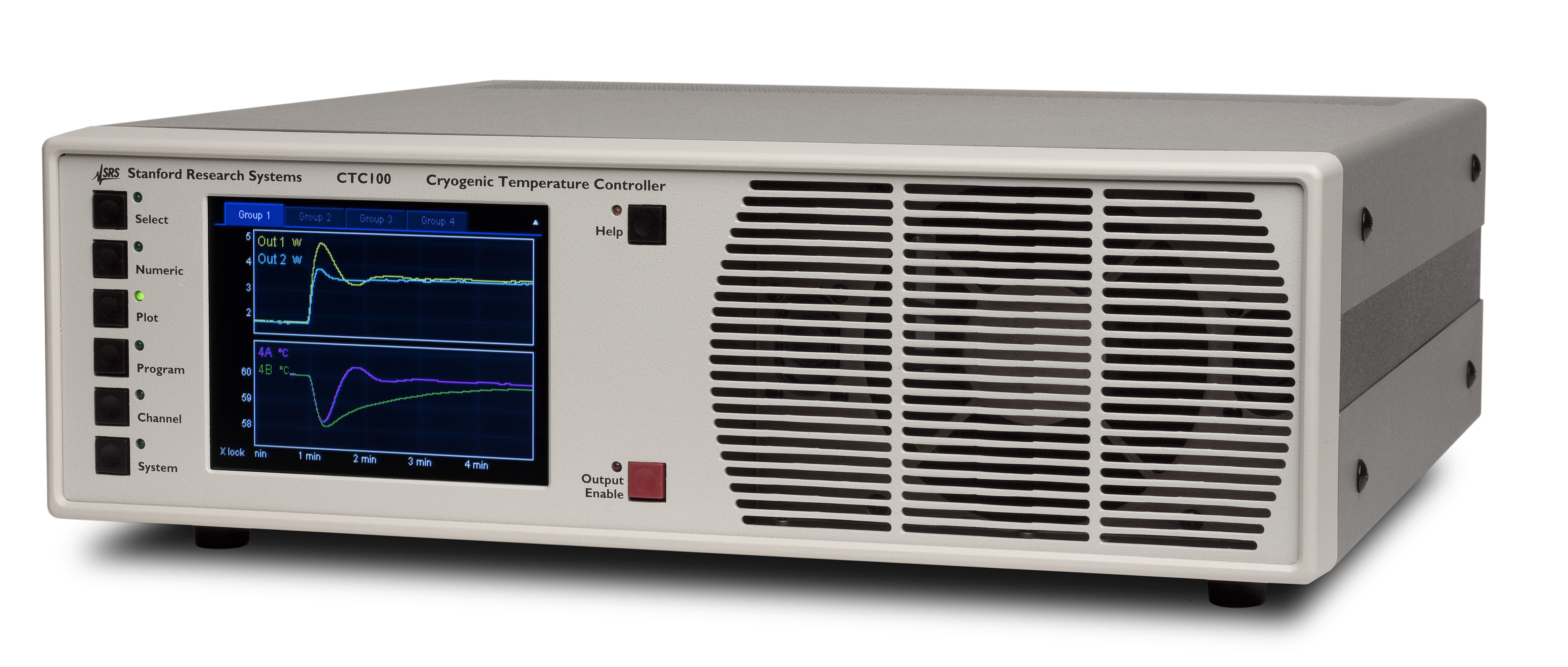
Search |
Home > Products > Scientific Instruments > PTC10 |
|
Temperature Controller | PTC10 ... from $1495 |
PTC10 — Programmable temperature controller |
(Click to enlarge) |
PTC10 Temperature Controller
|
Introducing the PTC10 Programmable Temperature Controller — the ideal instrument for measuring temperature, controlling heaters, and logging temperature data.
The PTC10 Programmable Temperature Controller is a modular system that can be configured to suit a wide range of applications. The system consists of the PTC10 Controller and up to four I/O cards — two types of input cards for RTDs and thermocouples, and two types of output cards for driving heaters. |
Related Products > CTC100 Cryogenic Controller > SIM921 AC Resistance Bridge > SIM922 Diode Temp. Monitor > SIM923 Pt RTD Monitor |
Downloads Datasheet User's Manual |
$ Prices |
PTC10 Programmable Temperature Controller
Introducing the PTC10 Programmable Temperature Controller from SRS — the ideal instrument for measuring temperature, controlling heaters, and logging temperature data.
The PTC10 Programmable Temperature Controller is a modular system that can be configured to suit a wide range of applications. The system consists of the PTC10 Controller and up to four I/O cards — two types of input cards for RTDs and thermocouples, and two types of output cards for driving heaters. The I/O cards are ordered separately, and you can mix and match them in any way you wish.
Input Cards
The PTC320 and PTC323 Thermistor/Diode/RTD readers can read a variety of resistive and diode temperature sensors. The PTC320 has a single input on a 6-pin circular DIN connector, while the PTC323 has two inputs on a 9-pin D-sub connector.
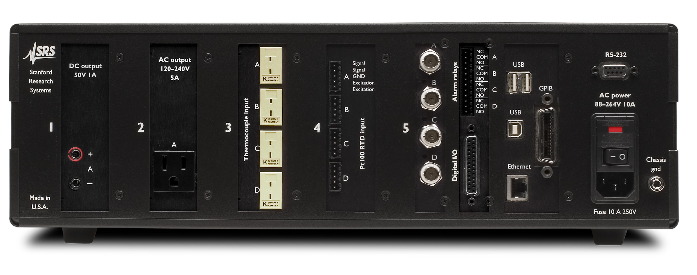
The PTC321 RTD reader has four inputs for 100 Ω platinum RTD sensors. Each channel has a four-wire input with its own 1 mA current source for sensor excitation. The current can be reversed with each reading to cancel out stray thermocouple EFMs.
The PTC330 four-channel thermocouple input card is factory configured to read either E, J, K, N or T type thermocouples. Each channel is electrically isolated allowing thermocouples to be attached to electrically-live equipment. An internal isothermal block, with its own RTD temperature sensor, provides highly accurate cold junction measurements.
Output Cards
The PTC420 AC output card is a heater driver that switches up to 5 A of 100 VAC to 240 VAC line current with a solid-state relay. The output power is controlled by switching the current on for some fraction of a 10 s cycle period and off for the remainder of the period. The PTC420 is intended to drive large heaters with response times of more than about 10 s. A PTC chassis can run up to two PTC420s at full power simultaneously.
The PTC430 and PTC431 DC output cards provide finer control for driving smaller, faster-responding heaters. The PTC430 delivers up to 1 A of current at 50 VDC, while the PTC431 delivers up to 2 A at 50 VDC.
The PTC440 TEC driver delivers ±5 A of current at ±12 VDC. This bipolar output card is optimized for driving thermoelectric coolers. It also includes a low resolution temperature sensor input that can read thermistors, RTDs, LM135, and AD590 sensors. For applications that require millikelvin resolution, a PTC320 card should be used with the PTC440.
A PTC chassis can run up to three PTC430s and/or PTC440s at full power simultaneously.PID Feedback
In a proportional-integral-differential (PID) feedback loop, the power supplied to a heater (the feedback output) is continually adjusted to keep a temperature reading (the input) at a predetermined value (the setpoint). The PTC10 offers up to six independent PID feedback outputs: one on each of up to two output cards, plus the four analog I/O channels. Any of the data channels can be used as the feedback input. PID feedback loops can be auto-tuned using either a single step response or a relay tuning method in which multiple steps create a temperature oscillation.
Data Acquisition and Display
All input channels are read simultaneously at rates between 1 Hz and the line frequency (50 or 60 Hz). Each input channel can be lowpass-filtered to reduce noise. Input channels can also be differenced with any other channel. Three “virtual channels”, which are not connected to any physical input, can display the results of more complex calculations..
Standard calibration curves are included for popular sensor types. Custom calibration curves with up to 200 points each can also be applied to any input; the curves are stored on a removable USB memory device and are loaded by simply plugging the device into the PTC10. Sensor calibration can also be adjusted by entering an offset and gain from the front panel.
The PTC10 has an internal data log that stores up to 4096 points per channel. Data can be written to the log at intervals between 0.1 s and 1 hr. The log rate can be set independently for each channel, or a global rate can be used. Data can also be logged to removable USB memory devices like flash keys, flash card readers, and USB hard drives. In this case, the maximum number of points that can be logged is determined by the size of the memory device.
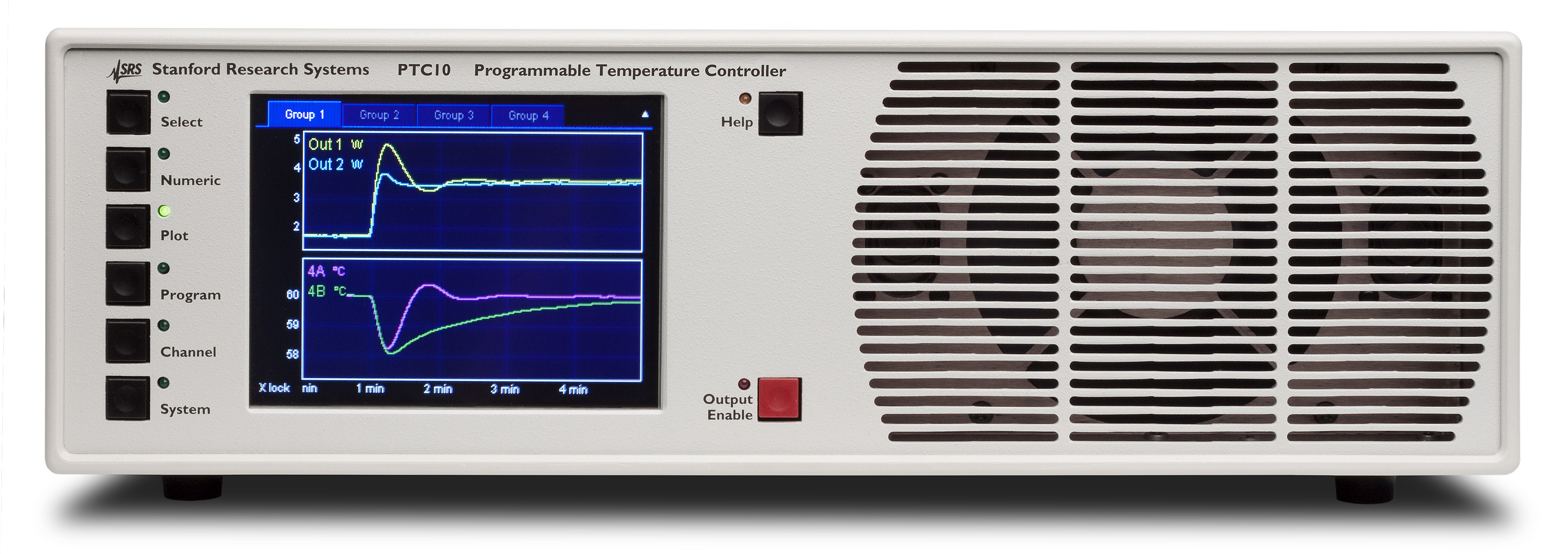
Input and output data can be displayed numerically or plotted on the LCD screen. Up to eight plots, each with up to eight data channels, can be displayed. You can zoom or pan the plots by touching or dragging your finger across the screen..
Upper/lower alarm levels or rate-of-change limits can be assigned to each input. If these limits are exceeded, an audible alarm sounds, a specified relay trips, and a specified output channel can be shut off. Alarms can be latching or non-latching.
Programmability
Remote operation is supported with USB, GPIB (opt.), RS-232, and Ethernet interfaces. All instrument functions can be controlled and read over any of the interfaces. When the USB interface is used, the PTC appears as a COM port on your PC.
The PTC10 supports user-defined macros that consist of one or more remote commands. Macros can be controlled from the front panel, and up to ten macros can run simultaneously. Macros can call other macros, and conditional statements, variables, and loops are supported. Using the PTC10’s three virtual channels, macro variables can be plotted on-screen, saved to logs, and/or used as inputs for feedback loops.
Macros are a powerful tool that can be used to tailor the behavior of the PTC10 for your experiment. For example, infinite-loop macros running as background tasks can take steps to address alarm conditions, automatically switch between sensor inputs (or heater outputs) depending on the current temperature or other factors, or implement cascade feedback schemes.
Multi-Purpose Ports
The PTC10 has four configurable general-purpose analog I/O channels, each of which can be used either as a 24-bit, ±10V input or a 16-bit, ±10V output. The PTC10 also has eight bidirectional digital I/O lines that can interact with macros, and four relays that can be tripped by alarms, remote commands, macros, or from the front panel.
The PTC10’s analog I/O channels can be used as feedback inputs, and custom calibration curves can be applied to convert their voltage readings into temperature, pressure, etc. values. If configured as an output, each analog I/O channel has its own PID feedback loop and can be interfaced with external equipment to control a heater or valve. The analog I/O channels can also be made to follow any other input or output, with scale and offset factors applied.
Flexibility
The PTC10 Programmable Temperature Controller has the flexibility to handle virtually any temperature application. It's as useful in the research lab as it is in industry. The PTC10 is the right choice for all your temperature control experiments.
PTC10 Programmable Temperature Controller | ||||
PTC10 Temperature Controller | ||||
Data acquisition rate | 1 to 50 Hz | |||
Temperature resolution | <0.001°C | |||
PID feedback | Both manual and auto-tuning modes are available | |||
Data display | 320×240 pixel touchscreen. Both numeric and graphical data display. | |||
Alarms | Upper and lower temperature limits. Rate-of-change limits can be set on each channel. If exceeded, an audio alarm and a relay closure will occur. | |||
Analog ports | ||||
# of ports | 4 configurable DAC or ADC ports | |||
Range | ±10 VDC | |||
Resolution | 24-bit input, 16-bit output | |||
Update rate | 50 Hz | |||
Connector | BNC | |||
Computer interface | USB, Ethernet, and RS-232. GPIB (IEEE488.2) is optional. | |||
Power | 10 A ;88 to 132 VAC or 176 to 264 VAC 47 to 63 Hz or DC |
|||
Dimensions | 17" × 5 " × 18 " (WHL) | |||
Weight | 25 lbs | |||
Warranty | One years parts and labor on defects in material and workmanship. | |||
PTC320 Thermistor/Diode/RTD Reader Card | ||||
Inputs | One input for 2-wire or 4-wire thermistor, diode or RTD | |||
Connector | 6-pin 240° push-pull DIN socket | |||
Thermistors | ||||
Range | Excitation current | Initial accuracy | Drift due to temp. | RMS noise |
30 Ω | 200 µA | ±0.025 Ω | ±0.002 Ω/°C | 0.003 Ω |
100 Ω | 100 µA | ±0.06 Ω | ±0.006 Ω/°C | 0.006 Ω |
300 Ω | 50 µA | ±0.1 Ω | ±0.006 Ω/°C | 0.012 Ω |
1 kΩ | 30 µA | ±0.2 Ω | ±0.01 Ω/°C | 0.02 Ω |
3 kΩ | 20 µA | ±0.6 Ω | ±0.03 Ω/°C | 0.03 Ω |
10 kΩ | 10 µA | ±1.3 Ω | ±0.1 Ω/°C | 0.6 Ω |
30 kΩ | 5 µA | ±4 Ω | ±0.15 Ω/°C | 0.1 Ω |
100 kΩ | 3 µA | ±10 Ω | ±0.5 Ω/°C | 0.3 Ω |
300 kΩ | 2 µA | ±250 Ω | ±3 Ω/°C | 3 Ω |
2.5 MΩ | 1 µA | ±30 kΩ | ±2000 Ω/°C | 25 Ω |
Diodes | ||||
Excitation current output | 10 µA | |||
Initial accuracy | ±100 ppm | |||
Drift | ±5 ppm/°C | |||
Voltage input | 0 to 2.5 V | |||
Initial accuracy | 10 µV + 0.01 % of reading | |||
Drift | ±5 ppm/°C | |||
RMS noise | 1.5 µV | |||
RTDs | ||||
Range | Excitation current | Initial accuracy | Drift due to temp. | RMS noise |
30 Ω | 5 mA | ±0.004 Ω | ±0.0006 Ω/°C | 0.00012 Ω |
100 Ω | 2 mA | ±0.008 Ω | ±0.001 Ω/°C | 0.0003 Ω |
300 Ω | 1 mA | ±0.02 Ω | ±0.0015 Ω/°C | 0.0006 Ω |
1kΩ | 500 µA | ±0.04 Ω | ±0.005 Ω/°C | 0.0013 Ω |
3 kΩ | 200 µA | ±0.1 Ω | ±0.01 Ω/°C | 0.003 Ω |
10 kΩ | 100 µA | ±0.2 Ω | ±0.03 Ω/°C | 0.006 Ω |
30 kΩ | 50 µA | ±1 Ω | ±0.06 Ω/°C | 0.012 Ω |
100 kΩ | 10 µA | ±2.5 Ω | ±0.2 Ω/°C | 0.07 Ω |
300 kΩ | 5 µA | ±16 Ω | ±3 Ω/°C | 0.25 Ω |
2.5 MΩ | 1 µA | ±30 kΩ | ±2000 Ω/°C | 25 Ω |
PTC323 Thermistor/Diode/RTD Reader Card | ||||
Inputs | Two inputs for 2-wire or 4-wire thermistor, diode, or RTD | |||
Socket | One DB9 (female) | |||
Diodes | ||||
Input Range | Excitation Current | Initial Accuracy | Temp. Drift (typ.) (at midrange) |
Noise (rms) (at midrange) |
0 to 2.5 V | 10 µA | 10 µV+ 0.01 % of reading | ±5 ppm/°C | 3 µV |
Thermistors | ||||
Input Range | Excitation current | Initial accuracy | Temp. Drift (typ.) (at midrange) |
Noise (rms) (at midrange) |
0 to 10 Ω | 1 mA | ±0.007 Ω | ±0.0002 Ω/°C | 0.0003 Ω |
0 to 30 Ω | 300 µA | ±0.03 Ω | ±0.0004 Ω/°C | 0.001 Ω |
0 to 100 Ω | 100 µA | ±0.07 Ω | ±0.002 Ω/°C | 0.002 Ω |
0 to 300 Ω | 30 µA | ±0.25 Ω | ±0.004 Ω/°C | 0.006 Ω |
0 to 1 kΩ | 10 µA | ±0.6 Ω | ±0.01 Ω/°C | 0.02 Ω |
0 to 3 kΩ | 3 µA | ±2 Ω | ±0.06 Ω/°C | 0.06 Ω |
0 to 10 kΩ | 1 µA | ±6 Ω | ±0.2 Ω/°C | 0.2 Ω |
0 to 30 kΩ | 300 nA | ±25 Ω | ±1 Ω/°C | 1.0 Ω |
0 to 100 kΩ | 100 nA | ±150 Ω | ±3 Ω/°C | 6 Ω |
0 to 300 kΩ | 30 nA | ±1 kΩ | ±20 Ω/°C | 40 Ω |
0 to 2.5 MΩ | 1 µA | ±1 kΩ | ±30 Ω/°C | 10 Ω |
RTDs | ||||
Input Range | Excitation current | Initial accuracy | Temp. Drift (typ.) (at midrange) |
Noise (rms) (at midrange) |
0 to 10 Ω | 3 mA | ±0.005 Ω | ±0.0001 Ω/°C | 0.0001 Ω |
0 to 30 Ω | 3 mA | ±0.005 Ω | ±0.0001 Ω/°C | 0.0001 Ω |
0 to 100 Ω | 2 mA | ±0.008 Ω | ±0.0002 Ω/°C | 0.0002 Ω |
0 to 300 Ω | 1 mA | ±0.015 Ω | ±0.0004 Ω/°C | 0.0003 Ω |
0 to 1 kΩ | 500 µA | ±0.05 Ω | ±0.001 Ω/°C | 0.0007 Ω |
0 to 3 kΩ | 200 µA | ±0.1 Ω | ±0.003 Ω/°C | 0.002 Ω |
0 to 10 kΩ | 50 µA | ±0.25 Ω | ±0.01 Ω/°C | 0.007Ω |
0 to 30 kΩ | 50 µA | ±1 Ω | ±0.02 Ω/°C | 0.008 Ω |
0 to 100 kΩ | 5 µA | ±4 Ω | ±1 Ω/°C | 0.12 Ω |
0 to 300 kΩ | 5 µA | ±13 Ω | ±2 Ω/°C | 0.2 Ω |
0 to 2.5 MΩ | 1 µA | ±1 kΩ | ±50 Ω/°C | 10 Ω |
PTC321 Pt RTD Card | ||||
Temperature range | –200 °C to 850 °C | |||
Inputs | Four 100 Ω Pt RTD 4-wire inputs | |||
Excitation | 1 mA | |||
Accuracy | ±30 mK | |||
Noise | 2 mKrms (10 samples/s) | |||
Temp. coefficient | 1.4 mK/°C | |||
Signal conditioning | Selectable 1 and 10 second time constant (digital LPFs) are provided. | |||
Signal detection | detects open and short circuit conditions. | |||
PTC330 Thermocouple Card | ||||
Thermocouple types | E, J, K, N, or T | |||
Temperature range | (range of calibration table with cold junction at 25 °C) | |||
E-type | -245 °C to 1025 °C | |||
J-type | -185 °C to 1225 °C | |||
K-type | -245 °C to 1395 °C | |||
N-type | -245 °C to 1325 °C | |||
T-type | -245 °C to 425 °C | |||
Inputs | Four thermocouple inputs | |||
Input capacitance | <1 pF | |||
Connector type | Omega mini thermocouple jacks | |||
Accuracy | ±500 mK (over 12 months) | |||
Noise | 20 mKrms (10 samples/s) | |||
Temp. coefficient | 20 mK/°C (type K thermocouple at 164.0 K) | |||
CMRR | 100 dB | |||
Common mode isolation | 250 VAC | |||
PTC420 AC Output Card | ||||
Output voltage | 120/240 VAC | |||
Max. output current | 5 A | |||
Cycle time | Adjustable between 1 and 240 s | |||
Max. line voltage | 250 VAC | |||
Surge current | 100 A max. (non-repetitive) | |||
Output resolution | 0.1 % at 10 s cycle time | |||
Heater resistance (min.) | 24 Ω (110 VAC), 46 Ω (230 VAC) | |||
PTC430 DC Output Card | ||||
Max. output voltage | 50 VDC | |||
Voltage ranges | 20 V and 50 V | |||
Max. output current | 1 A | |||
Current ranges | 0.1 A, 0.5 A, 1 A (50 V) or 2 A (20 V) | |||
Output resolution | 16-bit (24-bit with dithering) | |||
Accuracy | ±1 mA (1 A range) | |||
±0.1 mA (0.5 A range) | ||||
±0.01 mA (0.1 A range) | ||||
Noise (rms), 25 Ω load | 200 µV (2 A range) 15 µV (0.5 A range) 5 µV (0.1 A range) |
|||
PTC431 100 W DC Output Card | ||||
Output | One unipolar DC current source | |||
Connector | #6 screw terminals | |||
Range | 50V 2A, 50V 0.2A, 50V 0.02A, 20V 2A, 20V 0.2A, 20V 0.02A |
|||
Output resolution | 16 bit | |||
Accuracy | ±1mA (2A range) ±0.02mA (0.2A range) ±0.002mA (0.02A range) |
|||
Noise (rms) | (25 Ω load, DC to 10 Hz) 5 µA (2A range) 0.5µA (0.2A range) 0.05µA (0.02A range) |
|||
PTC440 TEC Driver Card | ||||
Output | One linear, bipolar DC current source | |||
Input | One 2- or 4-wire thermistor/RTD/IC temperature sensor input | |||
Connector | One 15-pin DB15-F | |||
TEC Driver | ||||
Output current | -5 A to +5 A | |||
Maximum power | 60 W | |||
Compliance voltage | 12 V | |||
Output resolution | 0.15 mA | |||
Accuracy | ±5 mA | |||
Temperature Sensor Input | ||||
Compatible sensors | ||||
Thermistors | 2- or 4-wire NTC thermistors | |||
RTDs | 4-wire platinum RTDs, 100 Ω to 1000 Ω at 0 °C | |||
IC sensors | LM335, AD590 or equivalent | |||
Excitation current | 10 µA, 100 µA or 1 mA | |||
Input range | ||||
Resistance | 1 Ω to 250 kΩ | |||
Voltage | 0 to 2.5 V | |||
Current | 0 to 1 mA | |||
Accuracy | ~100 mK. For critical applications, a PTC320 sensor card should be used. | |||
![]() |
||||