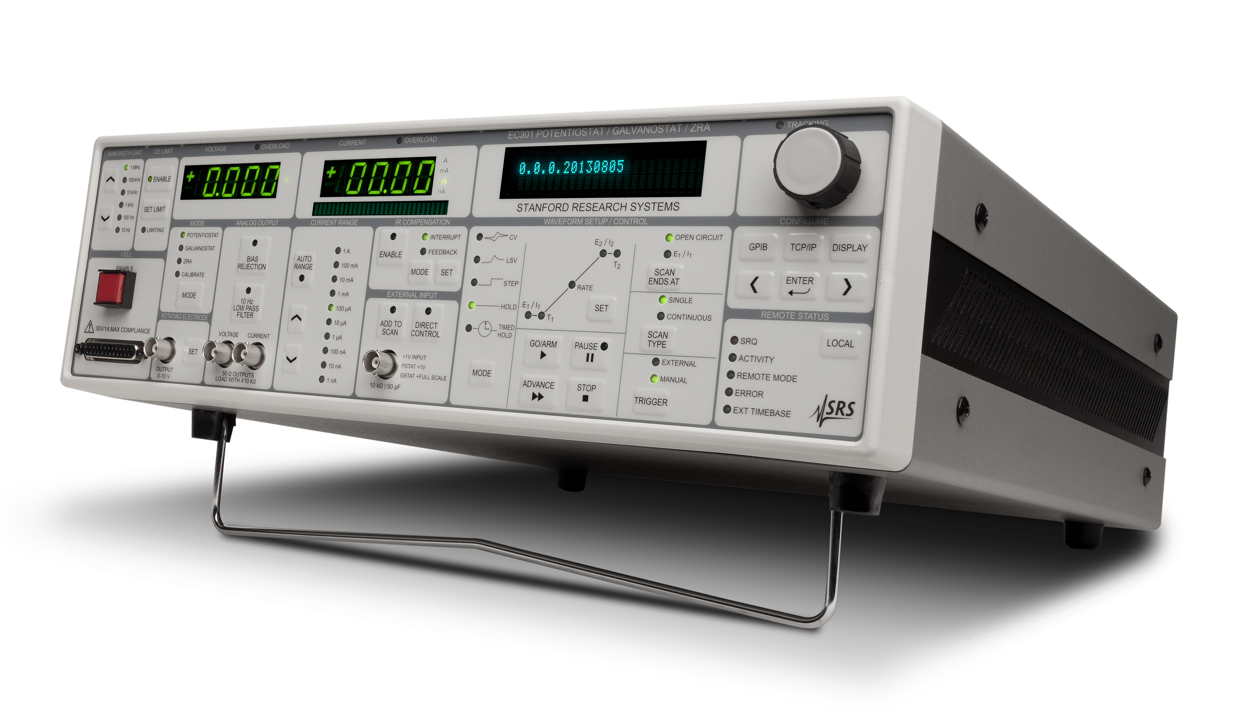
EC301


|
The EC301 gives electrochemists the opportunity to equip their labs with high compliance, research-grade instrumentation at a very attractive price. |
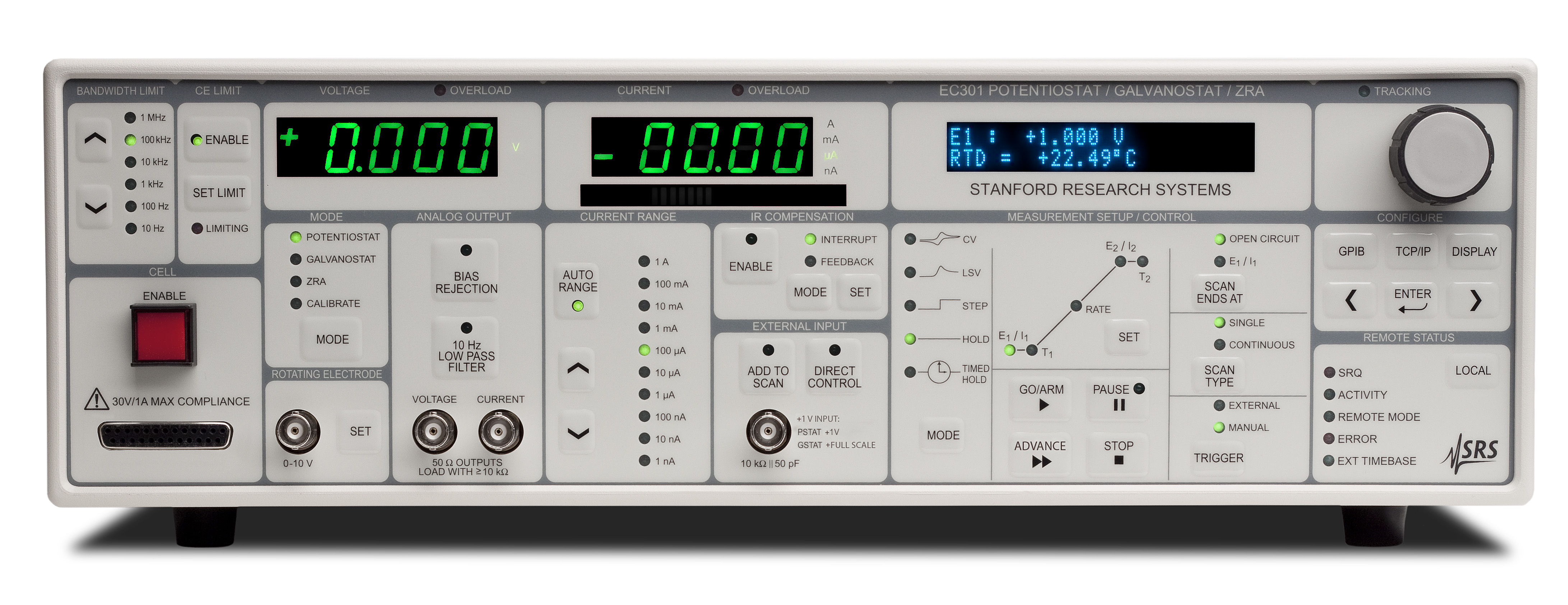
EC301

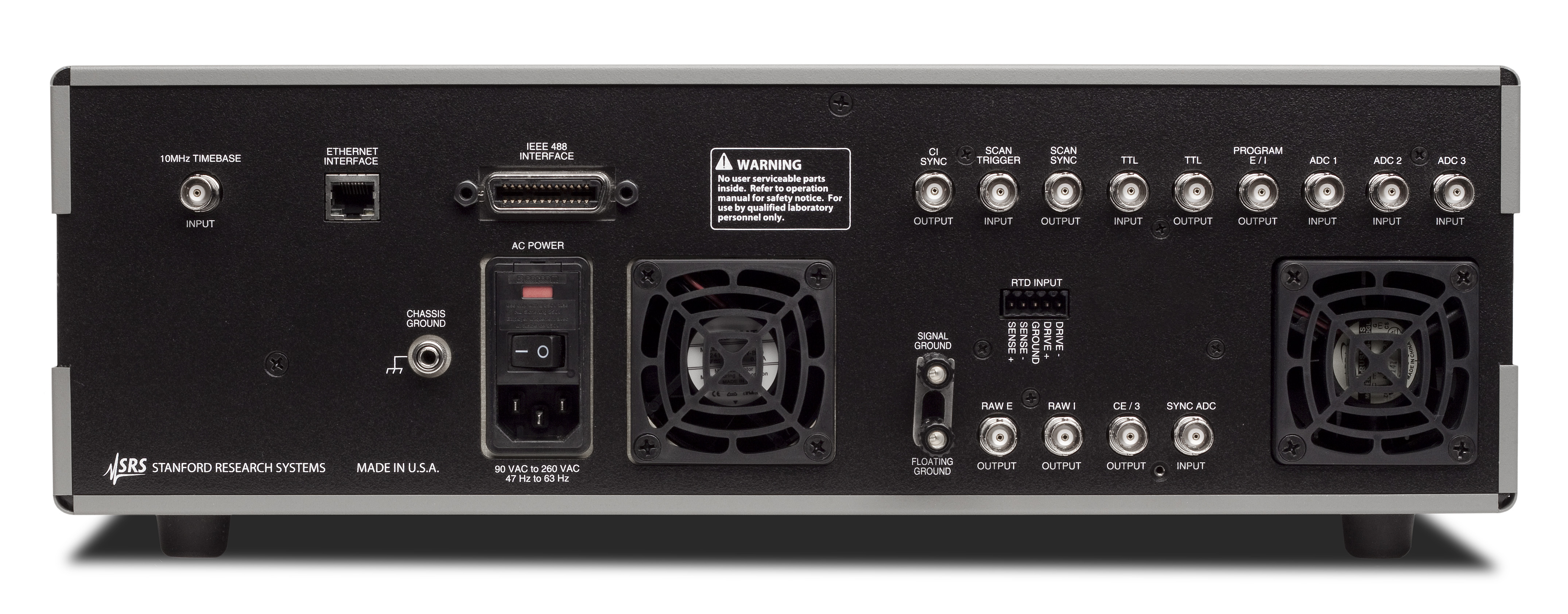
EC301

Getting started with SRSLab? Click the videos tab for instructional videos on how to use the software.
EC301 Potentiostat/Galvanostat
EC301 Potentiostat
The EC301 gives electrochemists the opportunity to equip their labs with high compliance, research-grade instrumentation at a very attractive price.
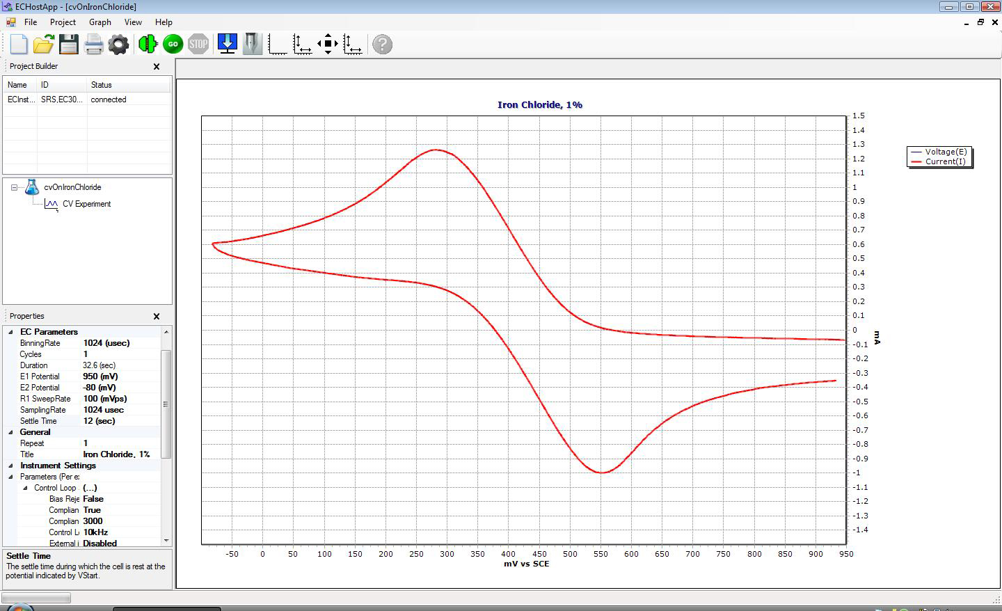
Cyclic Voltammetry (CV) — Iron ChlorideCyclic Voltammetry (CV) — Iron Chloride 
|
Front-Panel Operation
The intuitive front panel of the EC301 allows you to quickly and easily set up several scan types (CV, LSV, steps and holds). Unlike many competitive models, the EC301 is a stand-alone instrument—you don't need to use a computer. The array of indicator LEDs make it easy to know the state of the instrument at a glance.
Software Included
The SRSLab software supports all the major electrochemical techniques including voltammetry, pulsed waveforms, step techniques, and EIS. You can even design your own custom measurements. Data is acquired over the TCP/IP interface. The software lets you easily configure sequences of experiments and shows you the data as they are generated. The data is easily exported to spreadsheets and graphing packages.
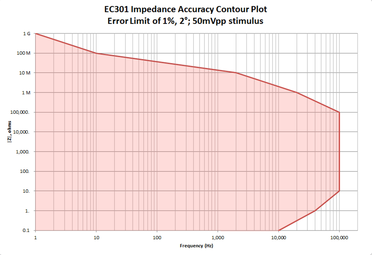
Impedance Accuracy Contour PlotImpedance Accuracy Contour Plot 
|
Designed for EIS
The EC301 was designed with electrochemical impedance spectroscopy (EIS) in mind. Instead of employing driven shields, we bring the measurement close to the cell. This means higher accuracy and less susceptibility to parasitic effects. Shunt resistor current measurements in all ranges enhance control loop stability, enabling EIS at high frequencies. An external frequency response analyzer (FRA) can be used measure EIS at frequencies up to 1 MHz using analog connections. The EC301 performs stand-alone EIS measurements up to 100 kHz.
Compliance Limiting
Quite often, electrochemists are working with sensitive cells which would be destroyed if the full compliance of a potentiostat were brought to bear. Bubbles in a flow cell system can easily cause potentiostats to lose voltage control by blocking feedback to the instrument from the reference electrode. Without compliance limiting, a carefully prepared electrode will be ruined. With this feature, the user can simply select the maximum potential the counter electrode will be allowed to apply. When the limit is reached, it is clamped to the preset level. Compliance limiting guarantees safe operation even if control is lost.
Optional Power Boosters
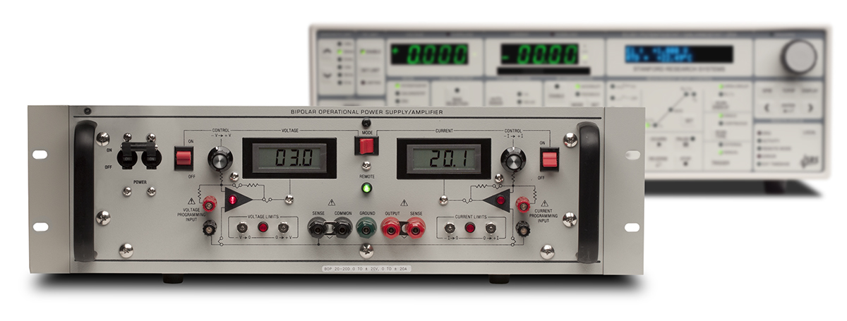
Optional Power BoosterOptional Power Booster 
|
SRS offers a ±5 A (O100BST), ±10 A (O200BST), or ±20 A (O400BST) power booster for applications requiring higher current. All three models are affordably priced.
Floating Working Electrode
In normal operation, the working electrode current return path is tied to chassis ground. However, there are times in which electrochemists wish to experiment with working electrodes that are intrinsically grounded (e.g., water pipes, rebar in concrete, an autoclave). Once the shorting bar from the rear panel of the instrument is removed, the ground return path floats, allowing these experiments.
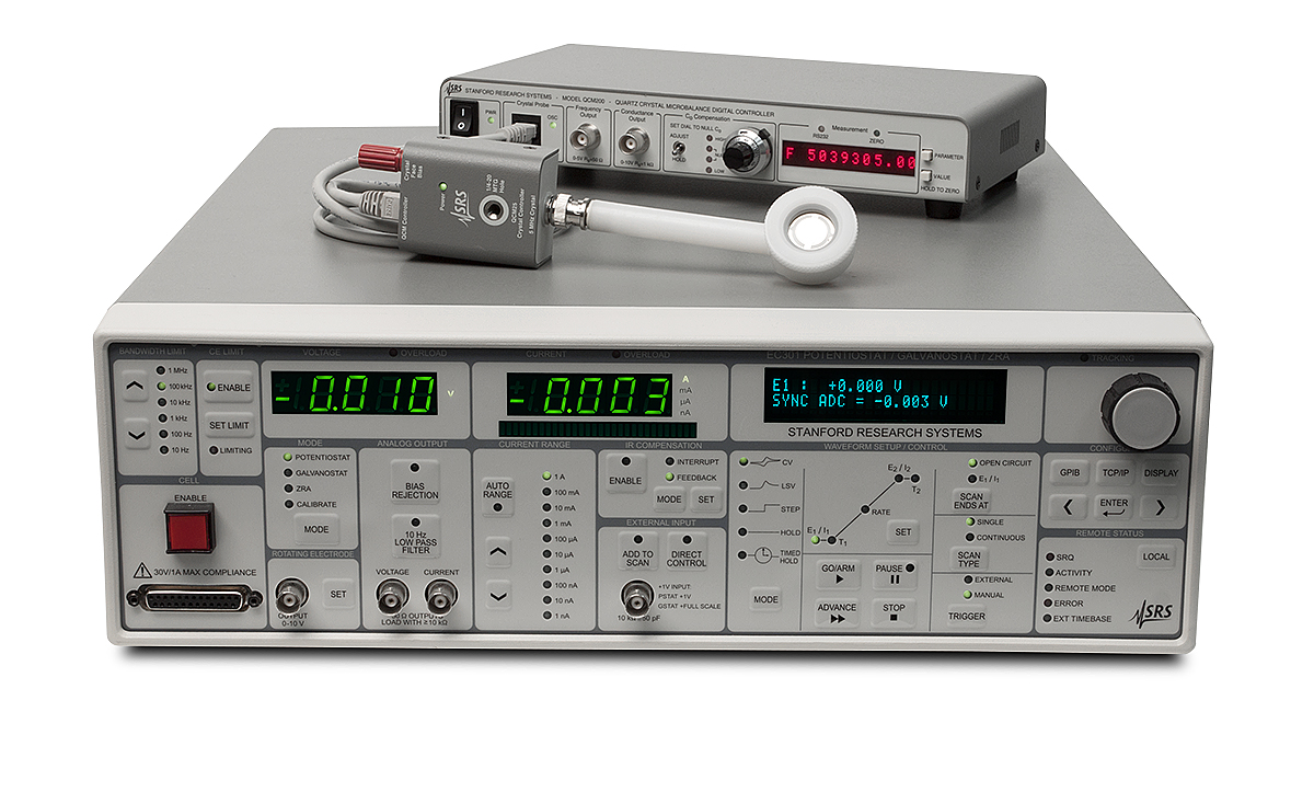
Quartz Crystal MicrobalanceQuartz Crystal Microbalance 
|
Fast Cyclic Voltammetry
The EC301 supports scan rates up to 10 kV/s. Potential, current and an auxiliary signal are all acquired simultaneously at 250,000 samples per second. Furthermore, an AC line detection circuit allows synchronization of repetitive scans with the power line cycle.
Built-in Temperature Measurement
Temperature is a critical parameter in many battery, fuel cell and corrosion experiments, but it is often not recorded. Not knowing the temperature at which the data were acquired can make it difficult to compare your results. With a built-in input for a 100 Ω platinum RTD, the EC301 makes it easy to acquire and plot temperature right along with the rest of your data.
Open Command Set
While our software supports all major electrochemical techniques, we realize that electrochemistry isn't static. When a new technique or procedure is developed, the open command set lets experimentalists write customized software to support it. You can write in LabVIEW, MATLAB, or any other language.

EC301 Specifications |
|
Power Amplifier (CE) |
|
| Compliance voltage | ±30 V |
| Maximum current | ±1 A |
| Bandwidth | 1 MHz (10 kΩ load, <100 µA) |
| Slew rate | ≥10 V/µs |
| CE limit | Limits counter electrode voltage when enabled |
| Set range | ±500 mV to ±30 V |
| Bandwidth | 1 MHz |
| Bandwidth limit | 10 Hz, 100 Hz, 1 kHz, 10 kHz, 100 kHz, 1 MHz cutoff frequencies |
Differential Electrometer (EC19 Module) |
|
| Input range | ±15 V |
| Input impedance | >1 TΩ in parallel with 20 pF |
| Input bias current | <20 pA |
| Bandwidth | >10 MHz |
| CMRR | >80 dB (<10 kHz) |
Potentiostat Mode |
|
| Applied voltage range | ±15 V |
| Applied voltage resolution | 500 µV (200 µV performing an automatic scan) |
| Applied voltage accuracy | ±0.2 % of setting ±5 mV |
| Automatic scan rate | 0.1 mV/s to 10 kV/s |
| Noise and ripple | <20 µVrms (1 Hz to 10 kHz) |
Galvanostat Mode |
|
| Applied current ranges | ±1 nA to ±1 A in decades |
| Applied current resolution | 16-bit |
| Applied current accuracy | |
| 1 A range | ±0.5 % of reading ±0.2% of range |
| All other I-ranges | ±0.2 % of reading ±0.2% of range |
| Automatic scan rate | 1 pA/s to 2 A/s |
Power Booster (Opt.) |
|
| Maximum current | ±5 A, ±10 A, or ±20 A |
| Compliance voltage | ±20 V |
ZRA Mode |
|
| Voltage offset | CESense and WE electrodes held within ±5 mV of each other |
Voltage Measurement |
|
| Range | ±15 V |
| Resolution | 16-bit |
| Accuracy | ±0.2 % of reading ±5 mV |
| Acquisition rate | 4 µs (250 kS/s) |
Current Measurement |
|
| Range | ±1 nA to ±1 A in decades |
| Resolution | 16-bit |
| Accuracy | |
| 1 A range | ±0.5 % of reading ±0.2% of range |
| (other ranges) | ±0.2 % of reading ±0.2% of range |
| Acquisition rate | 4 µs (250 kS/s) |
Analog Voltage and Current Outputs |
|
| Voltage output | ±15 V output |
| Accuracy | ±0.2 % of VRE - VWE Sense ±5 mV |
| Output impedance | 50 Ω |
| Max. output current | 10 mA |
| Filters | No filtering or 10 Hz low-pass |
| Bias rejection | ±15 V (full range) |
| Current output | ±2 V |
| Accuracy (1 A range) | IWE: ±0.5 % of (VBNC x IRange) ±0.2 % x IRange |
| Accuracy (other ranges) | IWE: ±0.2 % of (VBNC x IRange) ±0.2 % x IRange |
| Max. output current | 10 mA |
| Filters | No filtering or 10 Hz low-pass |
| Bias rejection | ±2 V (full range) |
IR Compensation |
|
| Positive feedback | |
| Range | 3 Ω to 3 GΩ (depends on current range) |
| Resolution | 1 mΩ (1 A range), 100 kΩ (1 nA range) |
| Current interrupt | |
| Switching time | <5 µs (1 kΩ resistive load) |
| Interrupt duration | 100 µs to 1 s |
| Interrupt frequency | 0.1 Hz to 300 Hz |
EIS |
|
| Mode | Potentiostatic / Galvanostatic |
| Frequency range | 1 mHz to 100 kHz |
| Dynamic range | 120 dB |
| Sweep | Linear or logarithmic |
Temperature Measurement |
|
| Sensor | 100 Ω Pt RTD |
| Accuracy | ±1 °C (-100 °C to +200 °C) |
Rotating Electrode Output |
|
| Range | 0 to 10 V settable analog output |
| Accuracy | ±1 % of setting ±5 mV |
External Input (front-panel BNC) |
|
| Input range | ±15 V (potentiostat mode), ±2 V (galvanostat mode) |
| Potentiostat mode | 1 V input corresponds to an applied voltage of 1 V |
| Galvanostat mode | 1 V input corresponds to an applied current of 1 A |
| Impedance | 10 kΩ in parallel with 50 pF |
| Bandwidth | >1 MHz |
| ADD TO SCAN button | Adds the external input voltage to internally-generated scans |
| DIRECT CONTROL button | Takes the control voltage or current solely from the external input |
Rear-Panel Inputs and Outputs |
|
| Timebase | 10 MHz, 1 Vpp |
| Raw E | ±15 V output |
| Raw I | ±2 V output (1 V full scale) |
| CE / 3 | ±10 V VCE / 3 voltage output, 1 MHz bandwidth |
| Sync ADC | ±10 V analog input |
| CI sync | TTL output for IR compensation |
| Scan trigger | Digital input. Falling edge begins automatic scan |
| Program E/I | ±15 V input (sum of internal and external voltage programs) |
| ADC 1,2,3 | ±10 V analog inputs (general purpose) |
SRSLab Software |
|
| Interface | TCP/IP |
| Operating system | Windows |
| Measurements | Cyclic Voltammetry (CV) Linear Sweep Voltammetry Cyclic Staircase Voltammetry (Tast) Square Wave Voltammetry Differential Pulse Voltammetry (DPV) Differential Normal Pulse Voltammetry (DNPV) Timed Hold Quartz Crystal Microbalance (QCM) Electrochemical Impedance Spectroscopy (EIS) |
General |
|
| Communication interfaces | IEEE-488.2 and TCP/IP |
| Dimensions | 17" × 5.25" × 19.5" (WHL) |
| Weight | 26 lbs. |
| Warranty | One year parts and labor on defects in materials & workmanship |
EC301 Specifications |
|
Power Amplifier (CE) |
|
| Compliance voltage | ±30 V |
| Maximum current | ±1 A |
| Bandwidth | 1 MHz (10 kΩ load, <100 µA) |
| Slew rate | ≥10 V/µs |
| CE limit | Limits counter electrode voltage when enabled |
| Set range | ±500 mV to ±30 V |
| Bandwidth | 1 MHz |
| Bandwidth limit | 10 Hz, 100 Hz, 1 kHz, 10 kHz, 100 kHz, 1 MHz cutoff freq. |
Differential Electrometer (EC19 Module) |
|
| Input range | ±15 V |
| Input impedance | >1 TΩ in parallel with 20 pF |
| Input bias current | <20 pA |
| Bandwidth | >10 MHz |
| CMRR | >80 dB (<10 kHz) |
Potentiostat Mode |
|
| Applied voltage range | ±15 V |
| Applied voltage resolution | 500 µV (200 µV performing an automatic scan) |
| Applied voltage accuracy | ±0.2 % of setting ±5 mV |
| Automatic scan rate | 0.1 mV/s to 10 kV/s |
| Noise and ripple | <20 µVrms (1 Hz to 10 kHz) |
Galvanostat Mode |
|
| Applied current ranges | ±1 nA to ±1 A in decades |
| Applied current resolution | 16-bit |
| Applied current accuracy | |
| 1 A range | ±0.5 % of reading ±0.2 % of range |
| All other I-ranges | ±0.2 % of reading ±0.2 % of range |
| Automatic scan rate | 1 pA/s to 2 A/s |
Power Booster (Opt.) |
|
| Maximum current | ±5 A, ±10 A, or ±20 A |
| Compliance voltage | ±20 V |
ZRA Mode |
|
| Voltage offset | CESense and WE electrodes held within ±5 mV of each other |
Voltage Measurement |
|
| Range | ±15 V |
| Resolution | 16-bit |
| Accuracy | ±0.2 % of reading ±5 mV |
| Acquisition rate | 4 µs (250 kS/s) |
Current Measurement |
|
| Range | ±1 nA to ±1 A in decades |
| Resolution | 16-bit |
| Accuracy | |
| 1 A range | ±0.5 % of reading ±0.2 % of range |
| (other ranges) | ±0.2 % of reading ±0.2 % of range |
| Acquisition rate | 4 µs (250 kS/s) |
Analog Voltage and Current Outputs |
|
| Voltage output | ±15 V output |
| Accuracy | ±0.2 % of VRE - VWE Sense ±5 mV |
| Output impedance | 50 Ω |
| Max. output current | 10 mA |
| Filters | No filtering or 10 Hz low-pass |
| Bias rejection | ±15 V (full range) |
| Current output | ±2 V |
| Accuracy (1 A range) | IWE: ±0.5 % of |
| Accuracy (other ranges) | IWE: ±0.2 % of (VBNC x IRange) ±0.2 % x IRange |
| Max. output current | 10 mA |
| Filters | No filtering or 10 Hz low-pass |
| Bias rejection | ±2 V (full range) |
IR Compensation |
|
| Positive feedback | |
| Range | 3 Ω to 3 GΩ (depends on current range) |
| Resolution | 1 mΩ (1 A range), 100 kΩ (1 nA range) |
| Current interrupt | |
| Switching time | <5 µs (1 kΩ resistive load) |
| Interrupt duration | 100 µs to 1 s |
| Interrupt frequency | 0.1 Hz to 300 Hz |
EIS |
|
| Mode | Potentiostatic / Galvanostatic |
| Frequency range | 1 mHz to 100 kHz |
| Dynamic range | 120 dB |
| Sweep | Linear or logarithmic |
Temperature Measurement |
|
| Sensor | 100 Ω Pt RTD |
| Accuracy | ±1 °C (-100 °C to +200 °C) |
Rotating Electrode Output |
|
| Range | 0 to 10 V settable analog output |
| Accuracy | ±1 % of setting ±5 mV |
External Input (front-panel BNC) |
|
| Input range | ±15 V (potentiostat mode), ±2 V (galvanostat mode) |
| Potentiostat mode | 1 V input corresponds to an applied voltage of 1 V |
| Galvanostat mode | 1 V input corresponds to an applied current of 1 A |
| Impedance | 10 kΩ in parallel with 50 pF |
| Bandwidth | >1 MHz |
| ADD TO SCAN button | Adds the external input voltage to internally-generated scans |
| DIRECT CONTROL button | Takes the control voltage or current solely from the external input |
Rear-Panel Inputs and Outputs |
|
| Timebase | 10 MHz, 1 Vpp |
| Raw E | ±15 V output |
| Raw I | ±2 V output (1 V full scale) |
| CE / 3 | ±10 V VCE / 3 voltage output, 1 MHz bandwidth |
| Sync ADC | ±10 V analog input |
| CI sync | TTL output for IR compensation |
| Scan trigger | Digital input. Falling edge begins automatic scan |
| Program E/I | ±15 V input (sum of internal and external voltage programs) |
| ADC 1,2,3 | ±10 V analog inputs (general purpose) |
SRSLab Software |
|
| Interface | TCP/IP |
| Operating system | Windows |
| Measurements | Cyclic Voltammetry (CV) Linear Sweep Voltammetry Cyclic Staircase Voltammetry (Tast) Square Wave Voltammetry Differential Pulse Voltammetry (DPV) Differential Normal Pulse Voltammetry (DNPV) Timed Hold Quartz Crystal Microbalance (QCM) Electrochemical Impedance Spectroscopy (EIS) |
General |
|
| Communication interfaces | IEEE-488.2 and TCP/IP |
| Dimensions | 17" × 5.25" × 19.5" (WHL) |
| Weight | 26 lbs. |
| Warranty | One year parts and labor on defects in materials & workmanship |

Getting started with SRSLab? Click the videos tab for instructional videos on how to use the software.
SRSLab Software
SRSLab is software that lets you perform a wide array of electrochemical experiments. Whether you do analytical work with pulsed waveforms, examine kinetics of charge transfer with voltammetry, perform surface science with a quartz crystal microbalance, or look at complex impedance for EIS signatures, SRSLab can acquire your data.

Cyclic Voltammetry (CV) — Iron ChlorideCyclic Voltammetry (CV) — Iron Chloride 
|
SRSLab is Free
Unlike some competitors, SRS doesn't charge you for software "modules". The entire software package, including all techniques, is a free download from our web site. You can try it out right now - even without owning an EC301.
Getting Started
Learning any full-featured electrochemistry software suite takes some effort. There are many experiments, each experiment has its own parameters, and some experiments require multiple instruments. While the techniques are widely understood, each software package uses its own nomenclature to describe parameters. In order to make your transition to SRSLab easy, we've created very focused videos (see below) that show just how to set up your experiment. Pop-up windows show you what each parameter controls on a waveform.
Flexible Plotting
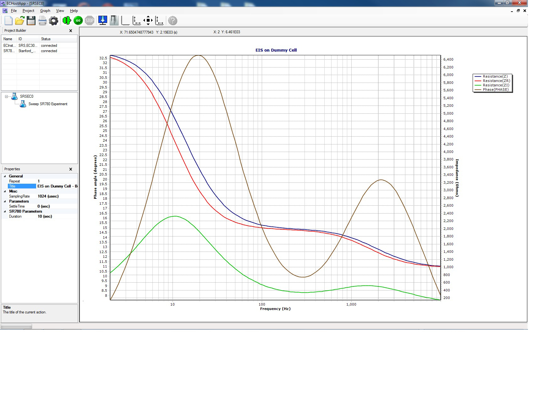
Electrochemical Impedance SpectroscopyElectrochemical Impedance Spectroscopy 
|
It can be frustrating to have to adjust your plotting preferences to match the software instead of the other way around. Maybe you want to flip the ordinate so anodic current is up instead of down. Maybe you want to plot negative potentials towards the right instead of the left. Maybe you need logarithmic axes. SRSLab's axis editor makes these preferences available with a single click. Sometimes you need to plot multiple data types on a single graph. SRSLab's Observables editor makes the plotting of complicated data intuitive and simple.
SRSLab Measurements
SRSLab covers the following techniques: Cyclic Voltammetry (CV), Linear Sweep Voltammetry, Cyclic Staircase Voltammetry (also known as Tast), Square Wave Voltammetry, Differential Pulse Voltammetry (DPV), Differential Normal Pulse (DNPV), Timed Hold, Quartz Crystal Microbalance (QCM), and Electrochemical Impedance Spectroscopy (EIS). (QCM and EIS require the QCM200.EIS to 100 kHz is built-in.) Galvanostatic versions of all of the above experiments are as easy as changing the instrument mode. A "free run" mode allows you to use your own stimuli (either via the external input or from your own custom waveforms) and acquire the response from the cell.
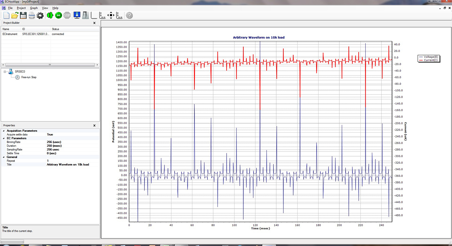
Arb Generated From a Random SignalArb Generated From a Random Signal 
|
If you have a typical set of experiments you like to run, you can add each one to an SRSLab project. When you begin running, SRSLab will run each of the experiments in sequence. A rotating green arrow indicates which experiment is running at any given time. When the sequence is finished, you can double click each experiment to quickly examine the results before you go to import them for data work-up.
Designed to Interface with Multiple Instruments
SRSLab was designed from the ground up to easily communicate with other instruments. This means that the software can control multiple EC301's, multiple QCM200's. When the instruments need to work in tandem, you add the instruments to the project, get connected, and you're ready to add your experiment. This flexibility also means that as SRS designs new instruments, you will be able to add them to SRSLab, getting your experiments going faster and easier.
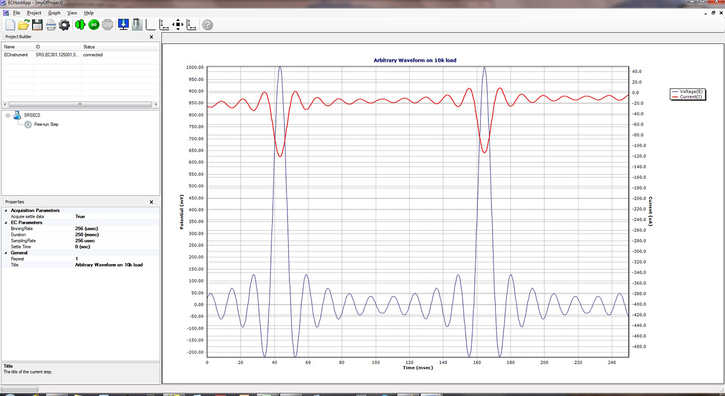
Arb Generated from Sinc(x) FunctionArb Generated from Sinc(x) Function 
|
Arbitrary Waveform Generator
SRS knows that electrochemistry isn't stagnant. Scientists come up with new techniques all the time. If you're working on a new kind of stimulus to the cell, you can use our arbitrary waveform generator. This allows an immense degree of flexibility. Programming the EC301 with the waveform is as easy as sending a file from within SRSLab.
Remote Programming
The remote interface is open and documented. Some competitors try to lock you in to their software by "closing" the remote interface. You don't get to "see" what happens over the interface to the hardware. The only experiments you can do are the ones defined by the software. This puts an intrinsic limit on you and your science. You can use a terminal window to see each and every command the software sends to the instrument over the Ethernet interface. This makes it very easy to use SRSLab as a template to develop your own custom techniques. You can write your own code in any language you wish. The manual thoroughly documents every command. With SRS, the only limit to your investigations is your own creativity.
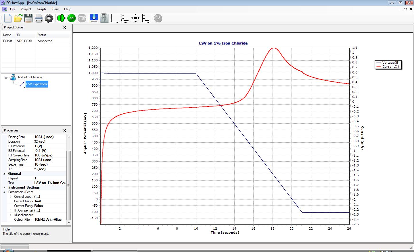
LSVLSV 
|
Exporting Data
Once you've acquired your data, you will likely want to import it into a spreadsheet or graphics package that you already know. SRSLab makes this easy. Export the data as tab-delimited ASCII or comma-separated ASCII. You can even specify the number of significant digits to use.
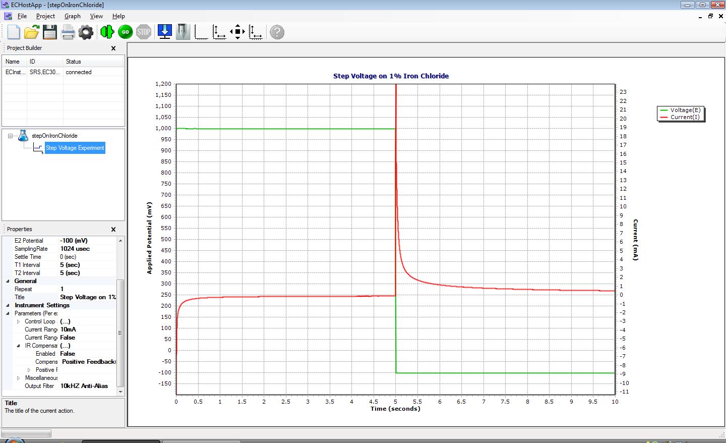
Step VoltageStep Voltage 
|
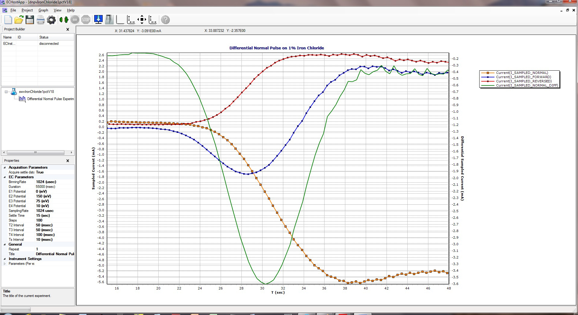
Differential Normal Pulse VoltammetryDifferential Normal Pulse Voltammetry 
|
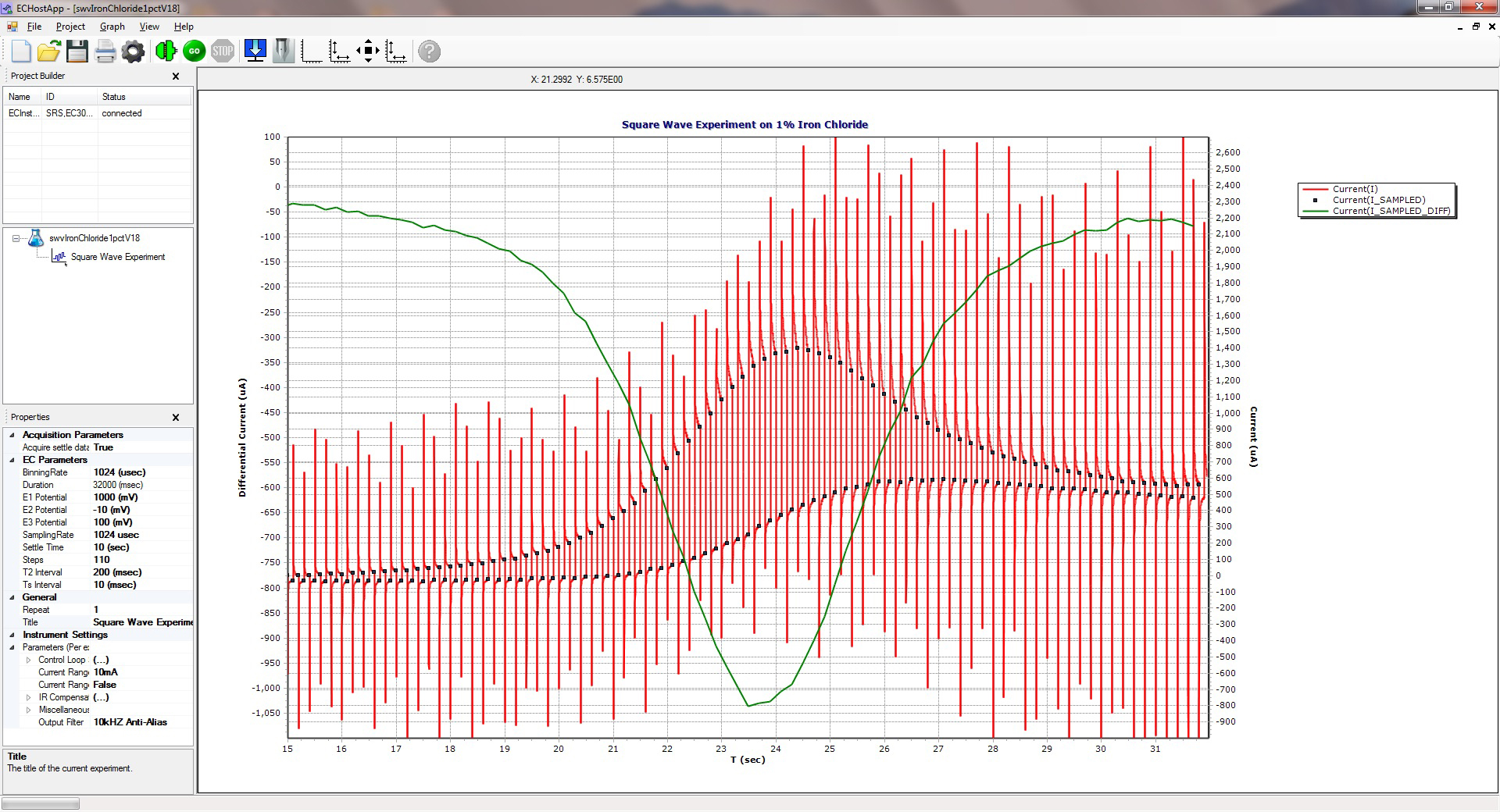
Square Wave VoltammetrySquare Wave Voltammetry 
|
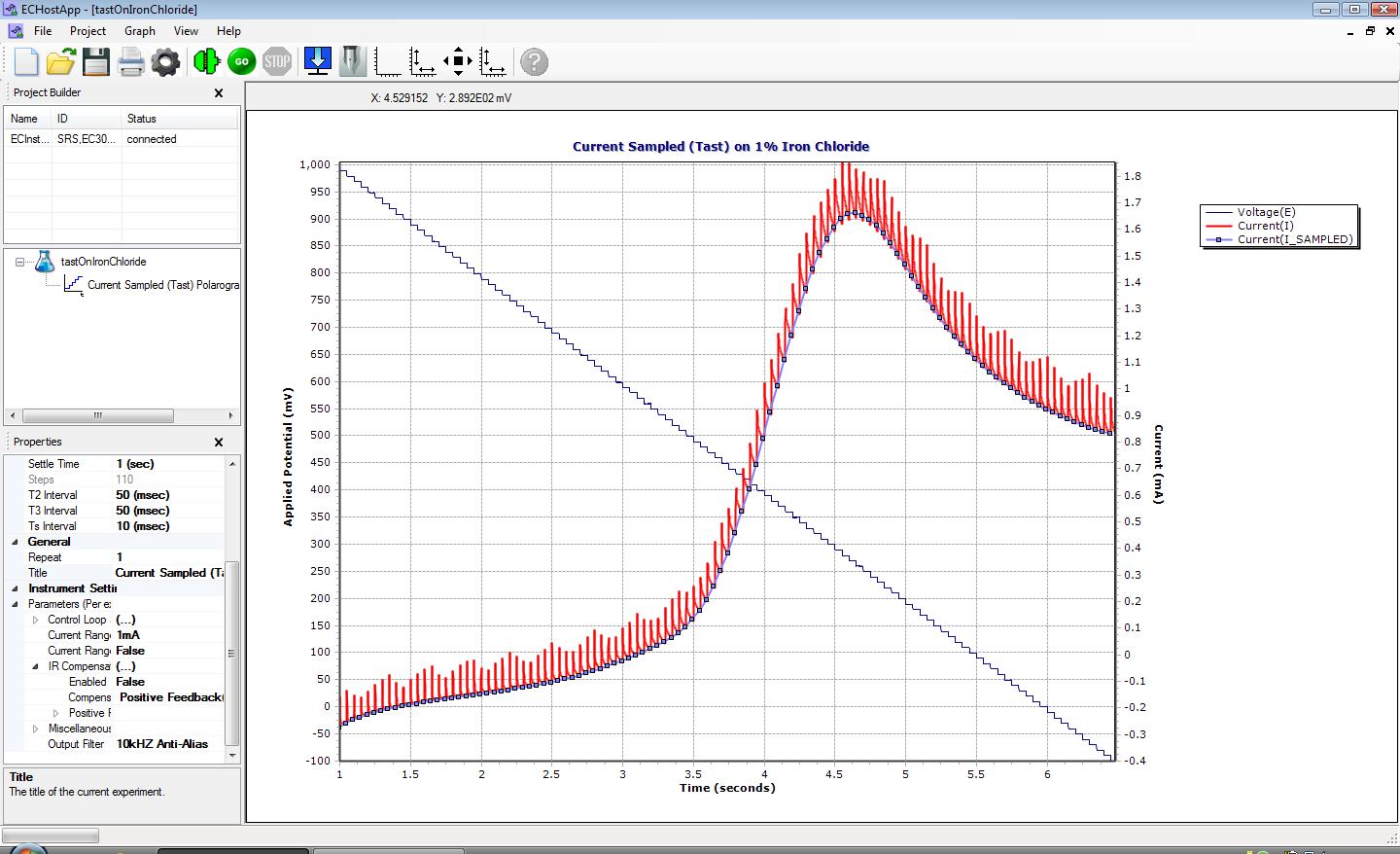
Cyclic Staircase VoltammetryCyclic Staircase Voltammetry 
|
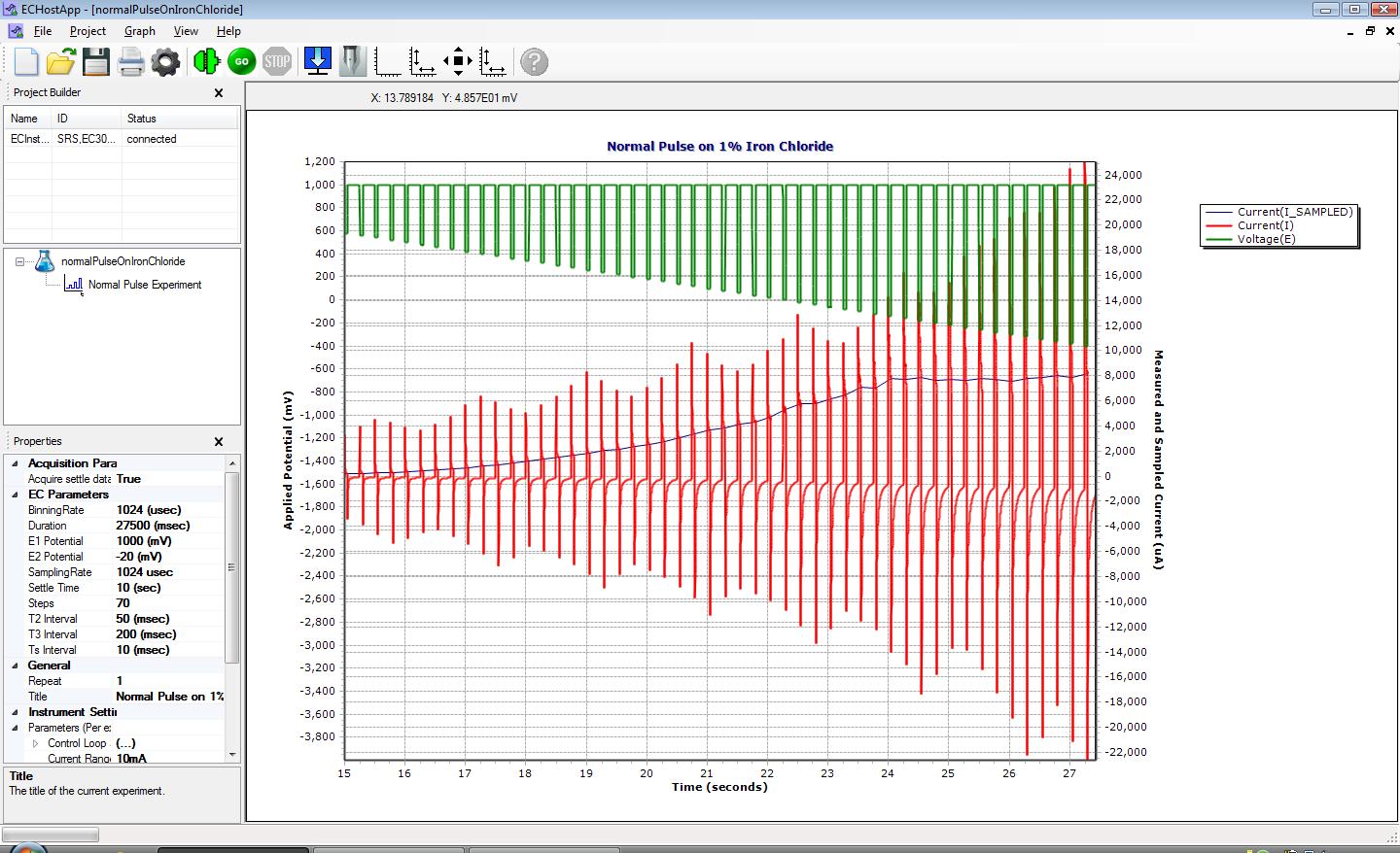
Normal PulseNormal Pulse 
|

To watch a documentation video, click its title (a link) on the left. (Windows Media Player is required)
| Getting Started | |
| firmware Update | How to update the EC301 firmware using SRSLab |
| introEc301Tcpip | Setting up your EC301's TCP/IP interface |
| adjustingTcpipOnFrontPanel | How to set up the TCP/IP parameters on the EC301 front panel |
| testingTcpipWithPingAndTelnet | Using a command-line interface to test your EC301's TCP/IP setup |
| gettingConnectedInSrsLab | How to connect to the EC301 over its TCP/IP interface in SRSLab |
| addingAndRemovingExperiments | How to add/remove experiment types within a project file |
| changingParameters | Changing defining parameters in SRSLab |
| RunningTestCV | Runs a test CV on a 10,000 ohm resistor |
| Changing the Graphing Window | |
| manualScalingAndMagPanTools | How to adjust the graphing window to your preferences |
| changingAxisLabelsAndTitles | How to change what the axis looks like in the graphing window |
| chartTitle | How to change the title for the entire chart in the graphing window |
| penEditor | How to use the pen editor for fine control over plots |
| observablesEditorIntroduction | An introduction to the observables editor, a flexible way to choose what you wish to plot |
| extraPoolOfObservables | How to customize your Observable Editor's interface |
| PlotCurrentWithOppositePolarity | Shows how a user-defined observable can switch the polarity of current |
| Instrument Control Parameters | |
| complianceLimiting | What compliance limiting is and why you should use it |
| addToScan | The effect of the front panel 'Add to Scan' control on the external input |
| biasRejection | What bias rejection is and what it does |
| controlLoopBandwidth | Shows how to change the EC301's control loop bandwidth to avoid oscillation |
| Data acquisition Parameters | |
| samplingRate | What the sampling Rate parameter is and when to change it |
| usingSettleTime | How to employ a settle time parameter in your experiments |
| binningRate | How to use binning rate to sub-sample your data on long experiments |
| Using the Terminal Window | |
| introTerminalWindow | How to invoke the SRSLab terminal which gives a command-line interface to the EC301 |
| eavesdropUsingTerminalWindow | See what remote commands are used by SRSLab to control the EC301 by 'listening in' |
| debuggingWithTerminalWindow | Using verbose mode in the terminal for debugging custom remote command scripts |
| Experimental Parameter Descriptions | |
| cvParameters | Covers the parameters in a cyclic voltammetry experiment and what they control |
| differentialPulseParameters | Covers the parameters in a differential pulse experiment and what they control |
| differentialPulseObservables | Shows what each DP observable is and how it is used in data work-up |
| freeRun | Free run is an "acquire only" mode of the EC301; this shows how to use it |
| Differential Normal Pulse Parameters | Covers the parameters of a DNP experiment and what they control |
| LSV Parameters | Covers the parameters of an LSV experiment and what they control |
| Normal Pulse Parameters | Covers the parameters of a normal pulse experiment and what they control |
| Timed Hold Parameters | Covers the parameters of a timed hold experiment and what they control |
| Staircase Parameters | Covers the parameters of a staircase pulse experiment and what they control |
| Squarewave Parameters | Covers the parameters of a square wave pulse experiment and what they control |
| Single Step Pulse Parameters | Covers the parameters of a single step pulse experiment and what they control |
| Data Export | |
| settingExportDataParameters | Configure the data export's significant digits, delimiters, etc. |
| selectingObservablesForExport | How to choose what ends up in your exported data file |
| exportingData | How to set up SRSLab to export to a tab delimited ASCII data file |
| printing | What the print preview looks like in SRSLab and how to use it. |
| Electrochemical Quartz Crystal Microbalance | |
| connectingQcm200ToEc301 | Shows how to connect the QCM200 to the EC301 |
| settingUpQcm200 | Three things you must setup before running an EQCM experiment |
| creatingFrequencyUserObservable | Shows how to make a user observable for the EQCM frequency |
| eqcmObservableDemo | Shows how to plot EQCM data using a real experiment with copper plating / stripping |
| Boosted Current Compliance | |
| boosterHardwareConnections | How to connect the booster and the EC301 |
| normalOperationToBoostedOperation | How to enter boosted operation mode on the EC301 front panel |
| boosterCheckoutOpenCircuitTest | Make sure the boosted system can run potentiostatically from -15 to +15V |
| boosterCheckoutShortCircuitTest | Make sure the boosted system can run galvanostatically over entire current range |
| boostedCyclicVoltammogram | Run a cyclic voltammogram on a short circuit load with the booster |
| boostedOperationToNormalOperation | How to return to normal operation from boosted operation via the front panel |
| Multi-Stat | |
| EC301 MultiStat | How to connect SRSLab to multiple EC301s to create a MultiStat |
| Electrochemical Impedance Spectroscopy without External Equipment | |
| canMyEc301doEisWithoutSr780 | How to tell if your EC301 can do a stand-alone EIS |
| TermCableConnectionsToUncompResistTestLoad | How to connect the EC301 to a test load for EIS |
| eisParameterDescriptions-noExternalEquipment | What the parameters mean in internal EIS |
| AcquiringInternalEis | Setup and acquisition of EIS on a test load |
| HowToPlotInNyquist | Plotting -Zim vs Zre |
| Electrochemical Impedance Spectroscopy with an SR780 | |
| AnalogConnectionsToSr780 | How to connect the EC301 to the SR780 analog connections |
| ConnectingAnSr780SerialPort | How to connect the SR780 to the PC |
| EisParameterDescriptions | Define what the SR780 EIS parameters mean |
| TermCableConnectionsToUncompResistTestLoad | How to connect the EC301 to a test load for EIS |
| AcquiringEisOnATestLoad | Tips on EIS acquisition with SR780 |
| HowToPlotInNyquist | Plotting -Zim vs Zre |
| MinorTicksInLogFrequencyPlots | Add minor ticks to your Bode plots |
| Miscellaneous Settings | |
| miscSettingsAdcFilters | How to change the filters in front of the potential and current analog to digital converters |
| miscSettingsEadcRange | Need to measure potentials greater than 2V? Change the range to 5 or 15V with this setting first |
| miscSettingsRotator | Using a rotating disc electrode? Set the speed with this setting |
| miscSettingsOutputFilters | Connecting the EC301 front panel outputs to external equipment? Set their filtering here |
| miscSettingsTimebase | Control whether you want to use the internal timebase or an external 10 MHz reference clock |
